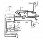
I have a diagram that explains the heater control vacuum lines but it doesn't match up well with what we're seeing on our car. Here is the diagram:
![]()
As you can see in the blue circle the Control Head has 6 lines coming out of it, it shows two lines going to the servos on the air inlet door and the mode door. Our servos only accept one vacuum line.
But that's not all!
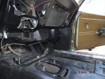
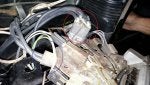
See this pic of our heater/AC control unit:
![]()
You can see we have 1 set of 4 lines, and one set of two. However, it was set up that one line connected the upper set to the lower. So we have effectively 4 lines going out. We believe we have 1 line each to the servos on the defroster door, the mode door, the air inlet door, and one going into the engine compartment that from the diagram appears to be split to the carb and to the heater water valve.
Is this right? What is the device on the diagram that is circled in red? Is there any way to identify what port goes where? On the diagram they are nicely numbered, but we don't see any numbers on our control unit. How do I identify what line goes where, and what is a check valve and that little device circled in blue with a 1 and 2 on it?
Thanks for any help!

As you can see in the blue circle the Control Head has 6 lines coming out of it, it shows two lines going to the servos on the air inlet door and the mode door. Our servos only accept one vacuum line.
But that's not all!
See this pic of our heater/AC control unit:
You can see we have 1 set of 4 lines, and one set of two. However, it was set up that one line connected the upper set to the lower. So we have effectively 4 lines going out. We believe we have 1 line each to the servos on the defroster door, the mode door, the air inlet door, and one going into the engine compartment that from the diagram appears to be split to the carb and to the heater water valve.
Is this right? What is the device on the diagram that is circled in red? Is there any way to identify what port goes where? On the diagram they are nicely numbered, but we don't see any numbers on our control unit. How do I identify what line goes where, and what is a check valve and that little device circled in blue with a 1 and 2 on it?
Thanks for any help!